Project Background
The embankments in most areas of Shanghai are located in soft soil areas. Embankments in soft soil areas often collapse due to geological conditions, hydrological conditions, climatic conditions, human factors, etc. The occurrence of collapses has a great impact on flood control and the safety of people’s lives and property. Repairing and rescuing collapsed embankments also consume a large amount of manpower and resources.
With the development of social economy, the construction of cross-river bridges is increasing gradually. At the same time, the erosion problem of bridge piers, abutments, and upstream and downstream flood walls is becoming more serious. Bridge piers and abutments have a significant impact on riverbed erosion, manifested mainly in several aspects:
1) obstructing water flow;
2) locally changing water flow;
3) affecting riverbed stability;
4) impacting aquatic organisms;
5) affecting the stability of underwater structures.
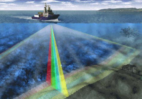
Multibeam measurement technology as an advanced survey method can provide technical support for studying the erosion effects on upstream and downstream riverbeds caused by bridge piers/abutments as well as flood wall impacts. This study aims to research the applicability of multibeam measurement technology methods to this study and investigate how they affect bridge piers/abutments as well as upstream/downstream flood walls erosion for providing scientific support for identifying and controlling safety risks related to bridges and flood walls.
Pain Point Analysis
▲Measurement ship mounted
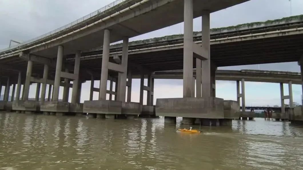
Traditional multibeam sounding systems require large ships for measurement, complex loading and unloading of sounding equipment. Fixed measurement ships carrying multibeam systems are suitable for deep water and open waters, generally used for ocean and lake measurements. The water surface narrows under bridge piers and platforms, with concentrated navigation traffic. Large survey vessels equipped with sounders lack flexibility, are easily disturbed during navigation, affecting the convenience and accuracy of measurements significantly.
Implementation plan
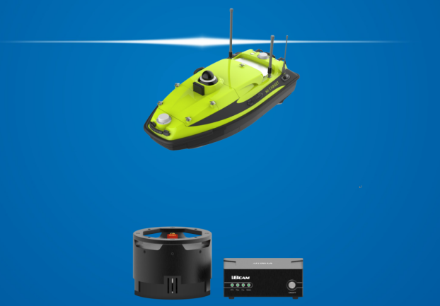
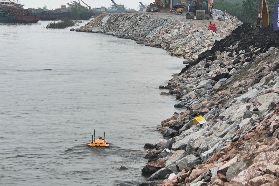
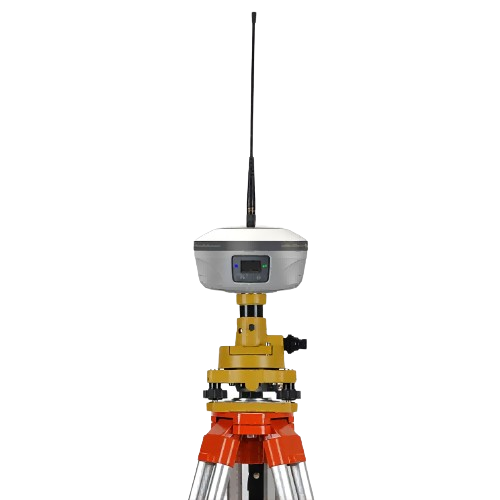
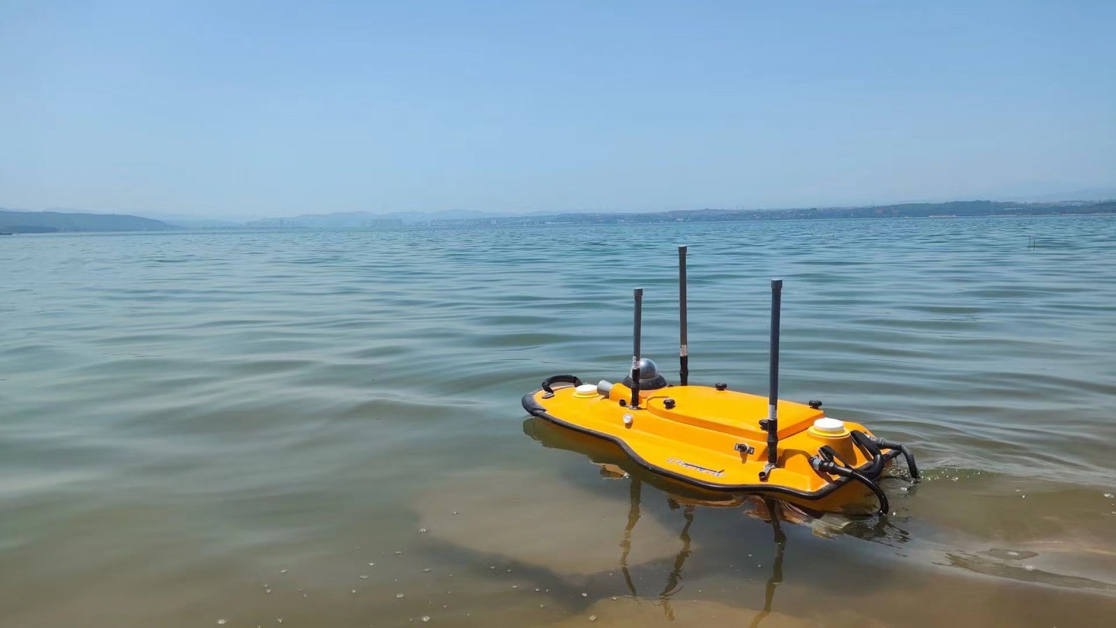
▲Unmanned boat portable
The multibeam sounding system is divided into measurement ship-mounted and unmanned boat portable according to the different platforms it carries. The measurement ship-mounted method belongs to the traditional multibeam sounding system, which requires a large hull for the measuring ship and complex loading and unloading of the sounding equipment. The fixed measurement ship-mounted multibeam method is suitable for deep water and open waters, generally used for ocean measurements and lake surface measurements. The unmanned boat portable multibeam sounding system has small size, high integration, convenient operation compared with traditional measurement ship-mounted multibeam sounding systems, with advantages such as safety, efficiency, high accuracy, good stability, and economy.
The study area for this research has relatively shallow water depth and a high volume of passing ships. Taking into account these factors, the research will utilize an unmanned boat with a portable multibeam echo sounder system.
Homework process
Field Data Collection
1.Line Layout
In the measurement range of this study, there are navigable vessels and water-resistant structures (such as bridge piers and platforms). The underwater terrain is deep in the middle and shallow on both sides. Vertical measurement lines are set up perpendicular to the river channel to cover the entire survey area; inspection lines are set up perpendicular to the measurement lines. To ensure data accuracy, the overlap of multibeam swath coverage should not be less than 50%.
2.Multibeam Calibration
Multibeam calibration mainly includes ship attitude calibration and depth measurement calibration. Attitude calibration includes roll, pitch, and yaw.
3.Determination of Navigation Speed
The flow direction and velocity in the interception harbor are affected by tides, causing turbulence. There is significant interference from passing vessels on the stable navigation of unmanned boats due to ship waves, ensuring safe navigation for unmanned boats and accurate data collection with multibeam technology. Considering various factors, the navigation speed control for unmanned boats during this data collection process is set at 2m/s.
4.Data Collection
Real-time control of data collection is carried out using HiMAX multibeam acquisition post-processing software developed independently by Zhonghaida (CHCNAV). Data collection stops when there is instability in system attitude caused by turning or reversing while sailing or due to ship wave effects on multibeam depth measurement systems.
At the same time, survey technicians adjust gain parameters based on real-time underwater conditions displayed by software interface.
Refer to Figure for Multibeam Measurement Control Interface.
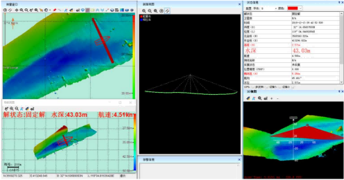
▲Multi-beam measurement software control interface diagram
Data post-processing and mapping
Through the multibeam acquisition post-processing software, the measurement data is processed as follows:
1.Create a new project to import survey lines: Import the data that needs to be processed into multibeam acquisition post-processing software.
2.Parameter setting: Check and calibrate parameters. Calculate the geographic location of the set parameters.
3.Tidal correction: Select no-tide correction.
4.Sound speed correction: Select single-profile sound speed correction mode.
5.Data fusion: Apply the set parameters to trace sound lines in the survey lines, and recalculate the positions of beam points.
6.Data editing: View yaw, pitch, heave, heading, track data. If there are abnormal data, use sensor data editing function to process them.
7.Exporting results: Export processed beam point cloud data.
Achievement Display
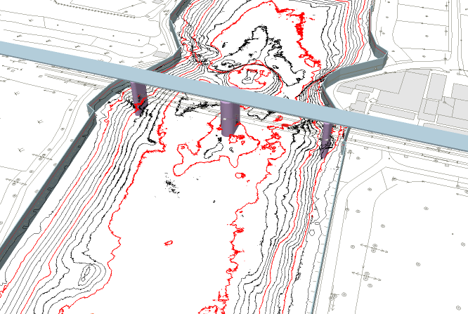
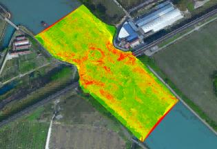
The underwater terrain within a 100-meter range upstream and downstream of the bridge, as well as the structure of the bridge piers, abutments, and flood walls were scanned in this study, generating multibeam survey data for two research points. The survey area covered 85,421 square meters, resulting in 8.8 million three-dimensional points with a density of 0.1m * 0.1m. The data was later processed, displayed, and analyzed using ArcGIS software.
Firstly, the software was used to process and transform the measurement data into TIN three-dimensional data.
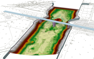
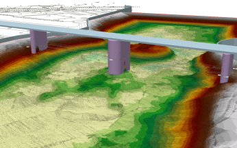
Secondly, ArcScene software was utilized to create solid gray models of the bridge piers, abutments, and flood walls at the research points based on their spatial positions. Subsequently, by overlaying the TIN data with these gray models and collected DWG digital line drawing data from multiple sources can visually display the topographic features of the study area. The overlaid map is shown below:
Project Summary
1.Applicability of multibeam systems
Through the analysis in this study, the data collected by unmanned ship multibeam bathymetric systems show high accuracy and can meet the needs for analyzing water-based structures and riverbed erosion.
2.Impact of bridge piers on river channel erosion
Analysis of field data from this study shows that bridge piers of cross-river bridges have an impact on erosion of the upstream and downstream river channels, typically leading to erosion gullies forming at the location of the bridge, with significant erosion observed in the riverbed near both upstream and downstream areas within a certain distance range from the bridge.
3.Influence of bridge piers on themselves and flood walls
Analysis of field data from this study reveals that near cross-river bridges, there is a noticeable steepening in slope along the riverbed near bridge piers, abutments, as well as flood walls upstream and downstream. This increase in slope poses a risk for scouring instability affecting foundations of bridge piers, abutments, and flood walls located nearby.