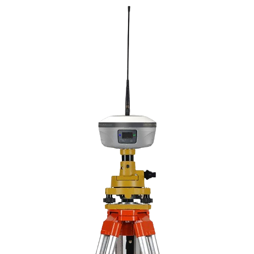
A surveying friend asked: Can RTK be used for control surveying?
The answer is: Yes.
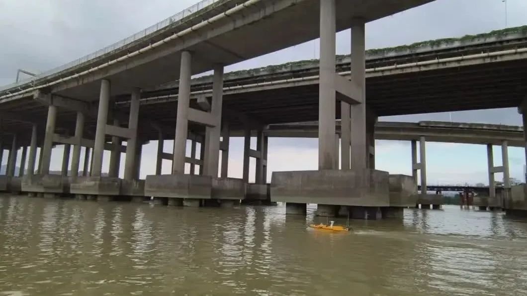
Can RTK be used for bridge stakeout?
The answer is: it depends on your situation.
The plane accuracy of RTK is generally 1.5-5cm, and the elevation accuracy is generally 2-5cm. The specific accuracy depends entirely on your terrain, working mode, control point accuracy, etc., and is not absolute.
In the past, when measuring the topographic map fragments, we used RTK to create root control points. The accuracy was not high. Although they were map roots, they were still control points.
If your bridge pile foundation deviation standard is ±5cm, and your RTK method can reach ±2cm after testing, ok, then of course there is no problem.
Simply put, the principle of RTK surveying is real-time kinematic positioning, which involves spatial distance resection. In other words, it is a real-time differential measurement system that utilizes base stations to transmit real-time differential data to your mobile station through a certain method. Subsequently, after coordinate transformation, engineering coordinates are displayed on your handheld device.

No matter what mode, this is the basic working principle.
This base station can be your own base station or the manufacturer’s base station.
RTK is a commonly used tool for point positioning surveying and stakeout. In 2006, I started using RTK for collecting scattered point data on topographic maps for the first time. It was not difficult, and I learned it in half a day.
This article addresses the following four questions:
1) The working principles of various modes
2) How to choose the appropriate mode
3) How to improve RTK surveying accuracy
4) How to verify RTK accuracy.
1、Working principles of various modes
There are currently two main RTK working modes: radio 、network/CORS.
In terms of surveying accuracy from high to low, they are ranked as follows: radio、network/CORS.
However, this is not absolute. The accuracy of any mode depends on the actual situation. Let’s briefly explain the working principles of various modes.
Radio: You need to set up your own base station, and one base station can support several mobile stations. The differential signal is sent from your own base station to the mobile station for correction.
Network/CORS: Through base stations built by various manufacturers, the differential signal is sent to you via these base stations.
Therefore, the accuracy of RTK largely depends on the distance between the base station and the mobile station as well as your own base station. The farther the distance from the base station to your mobile station, both its inherent precision and transmission over long distances may lead to loss in accuracy resulting in lower precision. Conversely, if the base station is close to your mobile unit, then there will be higher precision.
Radio:
You establish your own base station, and then the differential signal is directly transmitted to your mobile station through the base station via radio waves (this may not be accurate, but can be imagined as direct transmission like a walkie-talkie). If this transmission process is in a flat area, the accuracy will be very high. However, if there are tall buildings or mountains blocking the signal during transmission, the accuracy will decrease because it is point-to-point propagation. Therefore, the flatter the area, the smaller the loss of accuracy.

Therefore, the radio mode is a working mode with the highest accuracy and minimal precision loss. Our company uses only radio mode. Radios are divided into built-in radios and external radios, but their working principles are the same. Each GNSS receiver has a small built-in radio, but its power is generally small, resulting in limited working radius. However, it is very convenient.
External radios need to be linked separately with the base station and set up an antenna through a power source. This way, the working radius will be larger (our company’s external radio’s working radius cannot exceed 4km. If it exceeds 4km, there will not be no signal but rather precision loss; if the project exceeds 4km then another base station needs to be set up.)
Network/CORS.
This working mode does not require you to establish your own base station. the manufacturer you purchased from (RTK manufacturers build their own base stations) will send differential signals to your mobile station. This way, you save money on buying a base station receiver, but purchasing an account also costs money, haha.
However, the distance that the differential data travels from the base station to your mobile station is beyond your control. The farther the base station is from your mobile station, the lower the accuracy; conversely, the closer it is, the higher the accuracy.
The problem is that you have no idea how far away the base station is from you and it’s difficult to accurately measure its precision.

2、How to choose the appropriate mode
- Bridge project: It is recommended to choose the radio mode and decide whether to use built-in or external equipment based on the length of the bridge, as high precision is required for bridge construction and errors cannot be made.
- Areas with poor signal in remote mountains or uninhabited areas: Choose radio mode because there may be fewer base stations built by manufacturers in these areas, and the signals you receive may have been transmitted from tens to hundreds of kilometers away. However, if you do not require high accuracy and only need a signal, it’s up to you.
- Urban areas: It is recommended to choose network mode because cities generally have more base stations with stronger coverage. Using large base stations to send differential signals will not be affected by interference from tall buildings like radios, resulting in better signals.
- Areas with poor signal and many tall buildings.:Choose radio mode with built-in equipment where the base station moves along with the rover station; this method is one that I prefer but it can be cumbersome as you need to bring two receivers every time you go out, set up the base station wherever convenient nearby then find a control point for calibration before surveying points nearby which results in very small errors due to direct transmission of signals from nearby base stations reaching ±1.5-2cm for both horizontal and vertical measurements on average
Emphasis:
Regardless of the mode, mobile stations and base stations need to receive signals from satellites in the sky, and simultaneously calculate real-time WGS-84 coordinates. The base station calculates differential data based on the four parameters (or seven parameters) you previously obtained, and then sends it to your mobile station for correction. Therefore, the premise is that both the base station and mobile station must be able to receive signals from satellites in the sky.
3、How to improve RTK surveying accuracy
Just find the nearest control point for correction: The closer your correction point is to your layout point, the more similar the terrain conditions will be. Especially when measuring elevation in mountainous areas, if you correct a point at the mountaintop and then lay out at the foot of the mountain, can the elevation be the same? You simply don’t know what “elevation anomaly” is and have no respect for it. Those who work in surveying must understand this thing called elevation anomaly and atmospheric refraction.
Use radio mode: You can choose between fixed base station and mobile base station depending on your conditions and needs, but this mode has the highest accuracy because differential signal transmission does not lose data.
Choose a good network account.
4、How to verify RTK accuracy
For example: a bridge project with a length of 8KM
First, connect a base station at the start of the project, use a control point to calibrate, and then measure a point every 1km from the start to the end of the project. Each point is collected ten times and the average is taken.
Then, starting from the end position, still connected to the base station at the start position, a control point at the end position is used as a correction point, and then a control point is measured every 1km, and each point is collected 10 times to take the average.
At this time, use a control point at the starting position for calibration, then collect a control point after walking 1km, then calibrate with this control point, then collect another control point after walking 1km, and calibrate with this new control point… repeat until all points are completed within 8km.
Back in the industry, I analyzed the maximum errors under various circumstances. My conclusion at that time was that the coordinate error of the first and second methods reached a maximum of 12cm and a height error of 15cm. For the measured points within 1ckm after the calibration point, the error is stable at around 1.5cm no matter how far away it is from the base station.
What I did in the end was to build a base station at the start position and the end position. Each base station controls a working radius of 4km. You can connect to the base station on that side, and the working radius after each calibration must not exceed 500m. Then, after each stakeout, point A must be calibrated and point B must be checked. If the verification error exceeds ±2cm, all stakeout points must be reset.
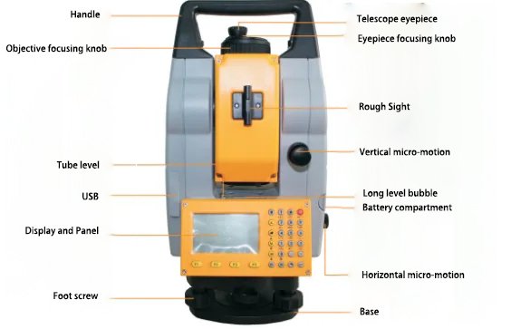
After such a wave of operations, there were no more than 5 inspections of point B exceeding 2cm in the entire project. However, the premise for this is that the distance between my control point and the basic control point is 150-300m. The control point is too far and the on-site measurement is carried out. It’s unrealistic. In addition, I used a total station for retesting and comparing the first few stakeouts.
Here is a special emphasis:
The terrain conditions of each project are different, so after entering the site, you should measure the maximum error of the mode you selected in advance to have an idea. Also, pay attention to the surrounding high-voltage lines and avoid them. This step cannot be skipped.


