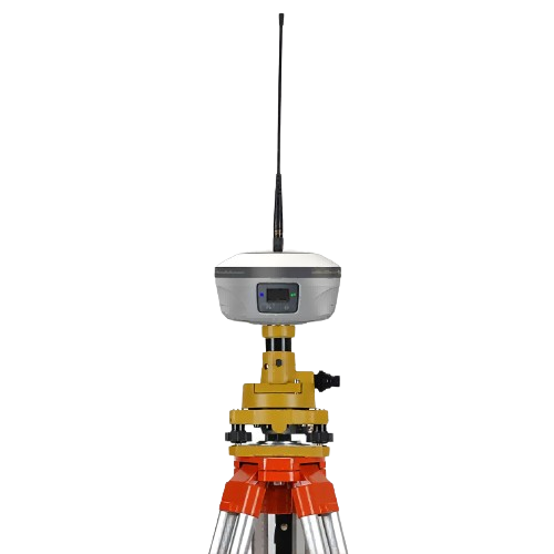
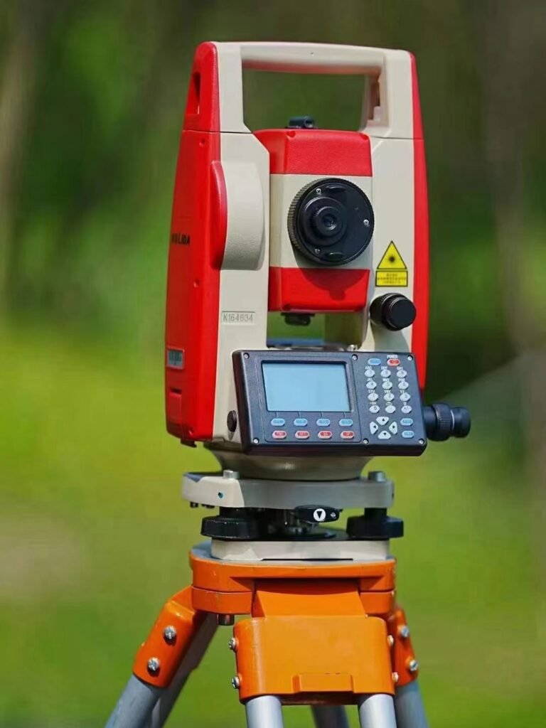
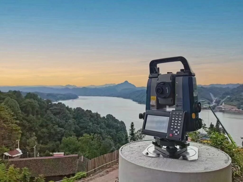
Total station. It is a high-tech measuring instrument that integrates optics, machinery, and electricity. It is a surveying instrument system that combines horizontal angle, vertical angle, distance (slope distance, horizontal distance), and height difference measurement functions. Because the instrument can complete all measurements at the station once it is set up, it is called a total station. Widely used in precision engineering surveys or deformation monitoring fields such as large-scale building construction on the ground and underground tunnel construction.
Introduction and Functions of Total Station
(1)Introduction to the appearance of the total station:
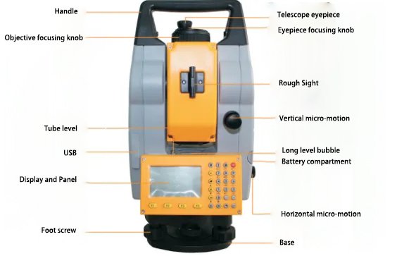
(2)Introduction of the functions of various components of the total station:
- Rough sight: Roughly aim at the prism or target object to facilitate locking onto the target with a telescope and improve aiming speed.
- Objective lens focusing knob: Adjust the distance and clarity of the target object in the telescope.
- Eyepiece focusing knob: Adjust the clarity of the crosshairs in the telescope. (Related to parallax)
- Instrument center mark: Distributed on both sides of the instrument, used for measuring instrument height.
- Horizontal brake knob: Located above the base, used to brake the horizontal rotation of the sighting part.
- Horizontal fine adjustment knob: This knob cannot be used alone and must be used after horizontal braking to precisely aim at the relative position of target objects and crosshairs in a horizontal direction.
- Vertical brake knob: Located on one side of the telescope, used to brake the vertical rotation of the aiming part.
- Vertical fine adjustment knob: This knob cannot be used alone and must be used after vertical braking to precisely aim at the relative position of the target object and crosshairs in the vertical direction.
- Circular level bubble: Used for rough leveling of instruments. If the bubble is on one side, it indicates that side is higher, relying on adjusting the extension of tripod legs to center the bubble.
- Tube level: Used as an indicator for precise leveling instruments, with scales on top. When the bubble is in the middle of a scale value, it indicates that the instrument is horizontal. Adjustment here mainly relies on three leg screws.
- How to determine the front and back of the instrument: One side of the tube level is the front, and the other side is the back, making it easy to determine whether the instrument is facing left or right.
- Prism mode (P) / Non-prism mode (NP): This mode determines how the total station aims at the target. In prism mode, the total station must be used with a prism. The center of the prism is where the target object is located. It requires using a combination of prism and centering rod during measurement, setting up prism height (the scale displayed on centering rod). If in non-prism mode, when measuring with a total station, you only need to aim at the target object without using a prism.
(3)Introduction to the buttons of the total station:
| Button | Name | Function |
|---|---|---|
 | Coordinate measurement key | Switch to coordinate measurement mode |
 | Distance measurement key | Switch to distance measurement mode |
 | Angle measurement key | Switch to angle measurement mode |
 | Menu key | In menu mode, you can perform measurements, query data files, set various parameters, and perform data transmission |
 | Exit key (return) | Return to measurement mode or previous mode |
 | Power key | Power switch |
 | Function key | Control the options at the bottom of the display |
 | Common function switch | You can quickly call up “lighting”, “contrast”, “EDM” |
(4)Operation of the total station:
Overall operation process: power on -> alignment -> rough leveling -> fine leveling -> realignment -> fine leveling again -> start measurement.
Step 1: Assemble the instrument, power on.
Step 2: Alignment. The total station is generally required to be set up above known control points for use, so the position of the control points must be found first. Use the optical alignment device or infrared alignment device of the total station to align it, so that the center of the instrument overlaps with the center of the control point as much as possible.
Step 3: Rough leveling. After alignment is completed, rough leveling of the instrument should be carried out by adjusting the height of tripod legs and observing changes in bubble positions in circular level vials. When half of a bubble enters into the circle, rough leveling is completed. (The standard operation is: fix one leg and only move the other two legs up and down; remember not to move all three legs together, otherwise it will cause misalignment of instruments and reduce efficiency in rough leveling.)
Step 4: Fine leveling. After rough leveling, rotate the aiming part to one side of the tube level, so that the tube level is parallel to the two foot screws. Fine leveling is mainly done through adjusting three foot screws. The specific operation is as follows: Adjust the two parallel foot screws with both hands, moving them inward or outward at the same time, so that the bubble in the tube level moves to the center of the scale. Then rotate the aiming part by 90° and only adjust the third foot screw so that the bubble in the tube level also moves to the center of the scale, completing fine leveling.
Step 5: Re-centering. By observing and controlling point positions with an optical collimator or infrared collimator, if two centers overlap, it means that instrument has completed re-centering and can proceed with subsequent measurement work; if they do not overlap, loosen knob connecting tripod and total station base slightly, gently move base until two centers align, then tighten knob securely at last.
Step 6: Fine leveling again. The second fine leveling does not require rough leveling, only fine leveling operation is needed. Follow the steps in the fourth step to complete it. After completion, rotate at any angle and observe whether the bubble of the tube level is centered, and check if the midpoint aligns with the center of control point. If both conditions are met, subsequent measurement functions can be used.
Step 7: Start measuring.
(Note: The condition for successful centering and leveling of the total station is that the instrument is completely centered, the level bubble in the tube is completely centered, and both conditions are met simultaneously. In general, achieving centering and leveling in one attempt is unlikely, so multiple repeated operations of centering and leveling are needed until both conditions are met simultaneously.)
(5)Introduction to the functions of the total station:
1) Angle measurement (select the “∠ or ANG” icon on the keyboard to enter angle measurement mode)
① Methods of distinguishing left and right discs (4 types): Here, the disc refers to the vertical circle. The disc on the left side refers to when the vertical circle is located on the left side of the telescope, it is called left disc; when it is located on the right side of the telescope, it is called right disc. However, nowadays total stations generally do not show the position of the vertical circle. You can also judge in this way: Method 1 – if eyepiece is to the left of centerline axis, it’s a left disc; if eyepiece is to right of centerline axis, it’s a right disc; Method 2 – during normal observation, if there is a tube level vial in front, it’s a left disc; if there isn’t one in front, it’s a right disc; Method 3 – alternatively through screen information (Ⅰ represents left disk and Ⅱ represents right disk).
② Meaning of Left Angle and Right Angle: Commonly seen in angle measurements such as HR/HL where H stands for horizontal angle and R/L stand for Right Angle and Left Angle respectively. This definition indicates whether you are measuring towards your route’s left or right direction. When measuring angles, choosing between Left Angle and Right Angle does not affect angle calculation but only affects reading size i.e., differentiating between internal angles and external angles. It’s recommended that before measurement begins, draw a rough sketch map which will help determine Left Angles from Right Angles easily. During measurements process switch between Left Angles and Right Angles should be avoided maintaining consistency throughout.
③Horizontal Angle: The symbol displayed in the instrument for horizontal angle is H (Horizontal), which is the angle between two straight lines in the horizontal direction. Therefore, it is necessary to measure the angles in two directions. The range of horizontal angle values is from 0° to 360°.
④Method of Measuring Horizontal Angle: When measuring an angle, choose the resection method for observation. The specific steps are as follows: Set up the total station at point O, sight and take a reading at point A with left faceplate, then sight and take a reading at point B; flip the telescope to right faceplate, first sight and take a reading at point B, then finally sight and take a reading at point A. The observation sequence is “A-B-B-A”. When measuring more than 2 angles, choose direction observation method (or full circle observation method) for observation. For left faceplate observation sequence: “A-B-C-D-E-A”, for right faceplate observation sequence: “A-E-D-C-B-A”.

⑤ Vertical Angle: The symbol for vertical angle in the instrument is V (Vertical). It refers to the angle between a straight line and the horizontal plane, with a range of -90° to 90°. Angles above the horizontal sightline are called elevation angles, while those below are called depression angles. The angle between them and the vertical direction is known as zenith distance.
2) Distance Measurement (Enter distance measurement mode, select the “◢” icon on the keyboard)
① Distance Measurement: Press the key to enter the ranging mode, aim at the center of the prism, click on measure or press Enter key to display slant distance (SD), horizontal distance (HD), and vertical difference (VD). These three measurements may not appear simultaneously and can be switched by pressing another key.
② When conducting traverse measurement, it is recommended to directly open the ranging mode. By measuring once, both angle values and distance values can be obtained simultaneously, simplifying measurement steps and saving time.
3) Coordinate Measurement
① Coordinate Measurement: Press the key (coordinate axis icon) to enter coordinate measurement mode. Aim at the center of the prism, click on measure or press Ent key to obtain coordinate values under a certain coordinate system (X, Y, Z or N, E, H). However, it is generally not used independently but commonly applied in specific project operations.
The application of total station in control measurement
①The application of total station in control measurement mainly lies in the use of triangulation method and traverse surveying method. By utilizing the angle and distance measuring functions of the total station, compared to traditional theodolites and steel tape for measuring angles and distances, it offers higher accuracy and efficiency. One observation can simultaneously obtain two types of measurement data.
In addition, the advantage of using a total station is that when aiming at a target, the precision is higher because measurements with a total station can be done in conjunction with a prism for reading observations. The prism can be directly set up above the target point, and alignment leveling can be achieved through base or centering pole to ensure the accuracy of measuring target position, reduce errors caused by aiming at targets, and improve measurement accuracy.
②Specific steps for traverse surveying: Firstly draw a rough sketch of traverse lines on paper to grasp the overall process of measurement. Then set up the total station at the first point, align it properly, switch to distance measuring mode, aim successively at previous control point and next control point as shown on traverse map. These two control points need to be used with tripods together with bases which should be aligned leveled or use centering poles so that prisms are positioned directly above these points. Finally aim at prism center with total station click measure button to obtain measurement data and record it. Subsequent operations for each control point follow similar steps until all control points have been measured once.
③Internal processing of wire measurement: The angular closing error is evenly distributed according to the average of the reverse symbols, and the coordinate increments are distributed proportionally based on the lengths of each side in reverse symbol; The calculation principle used is: forward computation of coordinates.
④Forward computation of coordinates: Using known point coordinates, azimuth angle, and distance to calculate the coordinate values of another point; Reverse computation of coordinates: Using the coordinates of two points to calculate the azimuth and distance of a straight line.
⑤Triangular elevation measurement: There are two methods for measurement, namely reciprocal observation method and intermediate point method. The reciprocal observation method involves measuring the vertical angle and slope distance (or horizontal distance) to target points using a total station, utilizing station elevation values to calculate target point elevations as shown in the figure below; The intermediate point method involves setting up a total station between known and unknown points, measuring vertical angles and slope distances or vertical distances to both known and unknown points, enabling calculation of unknown point elevations as shown in the figure below:


The application of total station in topographic mapping
- The application of the total station in topographic mapping mainly lies in the measurement of break points and elevation points. Break point measurement is mainly the process of collecting feature points, using prisms set up on feature points to complete the measurement. Relatively speaking, it is relatively simple and widely used.
- Precautions for topographic mapping: Each time the total station is relocated, it needs to be leveled, reset the survey station point and back sight orientation; after orientation is completed, re-measure the back sight point to check if its coordinate value error is within the allowable range. Only when it meets requirements can break point measurements begin; otherwise, re-leveling of equipment is required. During break point measurements, pay attention to changes in prism height; during the measurement process, ensure that survey point numbers match with sketch feature numbers.
- Steps for break point measurements: Create a new task → Input survey station points (coordinates and instrument height) → Orientation (manual or coordinate orientation) → Check back sight error → Start measuring (breakpoint measurement).
- Selection of orientation method: Choose manual orientation if azimuth angle is known; choose coordinate orientation if coordinates are known.
The application of total station in engineering construction measurement
1) The application of total station in engineering construction measurement mainly lies in surveying and setting out, including surveying during the reconnaissance phase, control measurements in the early stage of construction measurement, completion measurements after completion, as well as deformation monitoring. Control measurements, topographic mapping, and completion measurements (which are actually fragmentary measurements) have been introduced earlier and will not be elaborated here. This section focuses on the use of total station for setting out.
2) Methods of setting out measurement: 1) Polar coordinate method. First calculate the distance and azimuth between the setting-out point and measuring point, then set up the total station at the survey station point, set the azimuth angle correctly, and finally measure the target distance in that direction. 2) Coordinate setting-out method. Enter into setting-out mode first, input coordinates of the setting-out point or import coordinates of points to be set out; place a prism roughly at its position; then aim at the prism with a total station, click to measure to get a direction and distance indication deviating from the target point; move the prism according to indications for re-measurement until reaching the target point. 3) Intersection method. The intersection method includes distance intersection, angle intersection, axis intersection methods which obtain intersecting points by making circles intersect or angles intersect each other. 4) Adjustment method. By combining both setting out and measurement methods together: first set out a point through measurement; then obtain precise location of this point through multiple back-and-forth measurements; compare it with waiting-to-be-set points to get correction amount between them; finally determine accurate position for placing based on this correction amount.
3) Height difference measurement: Aim separately at two target points recording their elevation values; subtract these values from each other to obtain height difference (or altitude value).
Application of total station in deformation monitoring
- The application of total station in deformation monitoring mainly focuses on horizontal displacement monitoring, vertical displacement monitoring, and can also be used for incline observation of buildings.
- Methods for horizontal displacement monitoring: 1) Polar coordinate method. By measuring the angle and distance of the deformation point, the horizontal displacement value of that point is calculated; 2) Coordinate method. By directly measuring the three-dimensional coordinates of the deformation point, the horizontal displacement value of that point is obtained. When using a total station, it is necessary to select a measurement program, such as forward intersection or backward intersection, choose either one.
- Difference between forward intersection and backward intersection: Whether the survey station points are known or not determines which method to use – if known, it’s forward intersection; if unknown, it’s backward intersection. Backward intersection is also known as free-standing method and requires sighting at least three known points from behind to determine the coordinates of the survey station.
- Incline observation: Incline observation can be divided into two types – foundation incline and main body incline. Foundation incline requires measuring changes in settlement values at both ends while maintaining constant length (i=△h/L); main body incline involves measuring relative position changes between two points vertically from top to bottom while maintaining constant height. Typically, a right-angle corner of a building will be chosen for observations with a total station from two vertical directions to measure top-to-bottom displacement changes before calculating vector change △a and final calculation i=△a/H.
3-1024x941.jpg)
Application of total station in real estate surveying
The application of total station in real estate surveying mainly lies in the control measurement of trigonometric traverse and boundary point measurement, as well as the measurement of property elements. The principles and methods of boundary point measurement and property element measurement are the same as those in topographic maps, so they will not be elaborated here. The only difference is the content being measured. Topographic maps mainly measure terrain features, while property elements mainly focus on measuring characteristic points of buildings, with a greater emphasis on prismless observations and less concern for elevation values.
During real estate surveying, since the surveyed area is generally located in densely built-up areas, GNSS-RTK can be used in conjunction with a total station. GNSS-RTK is responsible for determining coordinates of specific points nearby to provide data for station points and back-sight points. The total station can directly utilize this data to measure property element characteristic points, thereby improving work efficiency.
Considering the various applications of total stations across different fields mentioned above, we can see that their uses primarily fall into two categories: one involves using measurements of angles and distances such as traverse surveys and polar coordinate method surveys; the other involves using measurements of three-dimensional coordinates at specific points like fragmentary point surveys or displacement observations.


